
High Speed Speed Signal Quality
USB 2.0 Specification, Section 7.1.2.2
For the High speed signal quality measurements USBET , USBHSET or High Speed Embedded Host Tester can be used.
Below two methods in measuring the High Speed Eye.
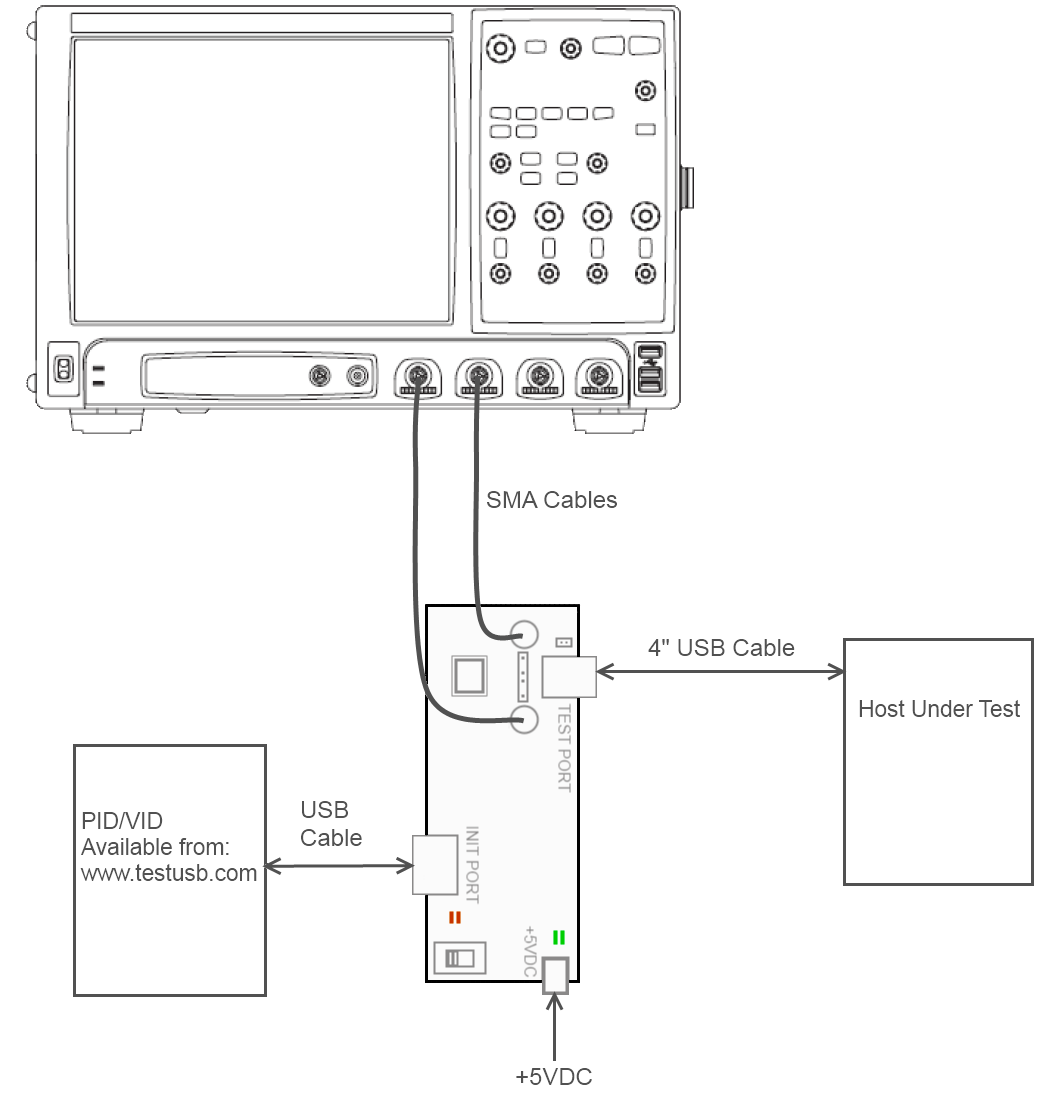
This measurment is also called the EYE diagram or signal integrity test. The device must be capable of sending the Test_Packet pattern (see USB 2.0 Spec 7.1.20) in order to perform the High Speed EYE diagram test. Note that USB 3.x products also need to meet these requirements. The product can be forced into test mode with the USBHSET tool for devices, hubs and standard host and the PIDVID for Embedded Hosts and OTG products. When a High Speed product has a standard, mini or micro receptacle the EYE diagram measurement is performed near-end. A High Speed test SMA fixture is required in order to do the tests. The 50 Ohm SMA cables are connected directly to the scope where the fixture compensate to 45Ohm. The distance from the device to the fixture should be kept as short as possible and therefore require very short cables or adapters. All USB-IF approved equipment can be purchased here.
If a device has a captive cable, vendor specific cable or direct A-plug the measurement is done far end. The EYE is smaller as the near end eye and therefore more relax the pass/fail criteria on the eye. Note that Thumbdrives also consider to have a captive cable.
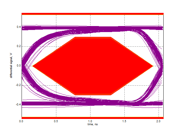
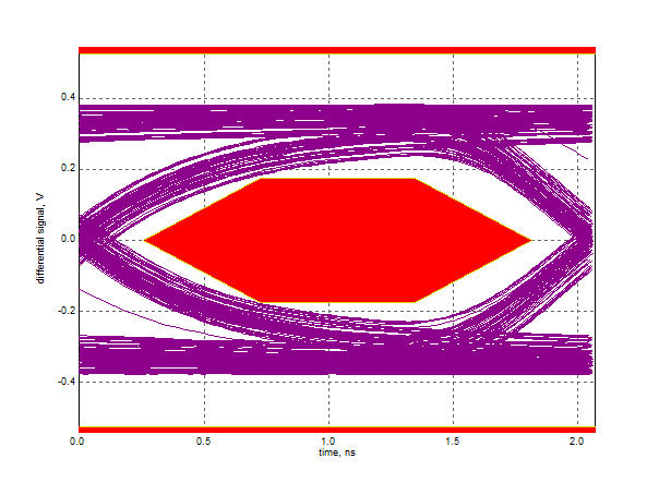
Near end High Speed EYE Far end High Speed EYE
It is advisable to perform these tests in an early stage of
the development.
Beside the USB-IF compliance EYE diagram it's advisable to
perform the real time eye.
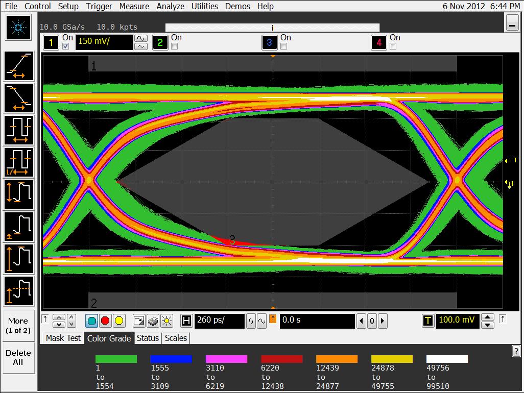
Download the Real Time EYE settings for an Agilent scope here. When using SMA pair download here and when using a differential probe here.
Using a certified USB silicon will give a USB developer a
certain guarantee that the product is capable of passing the eye
diagram test. However, there are still many items that could cause the
device to fail the eye diagram.
Common failures are:
- Bad PCB design (traces too long, traces not matched, interference
from another source,...)
- Bad cabling
- ESD, EMI components that do not meet the USB requirements
- Bad clock, PLL
- Ferrite beads and common mode chokes
- Not use the latest USBET
- Bad Test Fixtures
- Updates