Vbus Drop
USB 2.0 Specification,
Section 7.2.2
USB 3.x Specification, Section 11.4.2
On-The-Go and Embedded Host Supplement to the USB Revision 2.0
Specification, Section 4.2.1
Battery Charging Specification, Revision 1.2, Section 4.2.1
Vbus up to 5.5V ECN
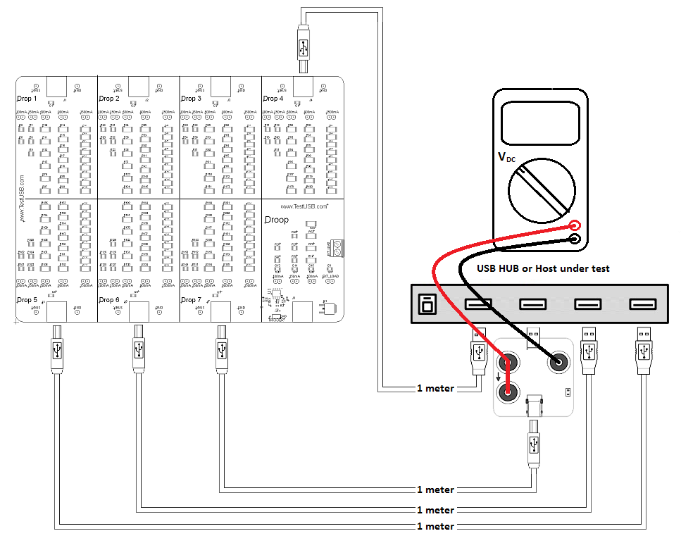
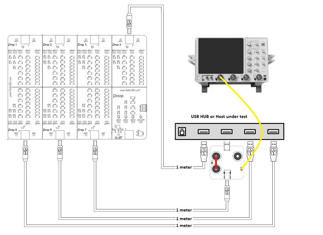
The
voltage drop test is a DC measurement that can be done with a regulare
DMM or Oscilloscope by measuring the
voltage over Vbus and GND on a fixture.
It's however too often products fail these requirements that cause serious problems in the market. The problems only increase now more devices taking more current for charging their batteries over USB.
For each downstream port Vbus should be measured without load and with all ports loaded with the worst case load. The voltage should never exceed the 5.5V. How much the load is for each port and how much the voltage may drop (Vbus min) depend on the following:
| Downstream
port under test |
Load (mA) | Vbus min (V) (*) |
| USB 2.0 Bus-Powered hub | 100 | 4.4 |
| USB 2.0 Self-Powered hub | 500 | 4.75 |
| USB 3.x Self-Powered hub | 900 | 4.75 |
| PC USB 2.0 Host system | 500 | 4.75 |
| PC USB 3.x Host system | 900 | 4.75 |
| Embedded Host & OTG- A USB 2.0 low power (TPL Imax <100mA) | TPL (**) | 4.4 |
| Embedded Host & OTG- A USB 2.0 high power (TPL Imax >=100mA) | TPL (**) | 4.75 |
| Embedded Host & OTG- A USB 3.x | TPL (**) | 4.75 |
| BC 1.2 CDP capable hub, host embedded or host port | 1500 | 4.75 |
(*) The Vbus min
values
of the above table are DC values and not take transient
voltage into account.
(**) The maximum load for an
Embedded host & OTG- A is
depending on the TPL.
When doing the measurement take
the cable resistance / voltage drop into account what can be significant with high currents. For example if you
have 0.25Ohm resistance for cable and connectors and a current
of
900mA you will have
a voltage drop of 0.225V. Therefore the
measurment should be done as near to the A-Receptacle as
possible and if accessible you can measure at the A-receptacle Vbus/GND
soldering pad. Measuring at the A-receptacle is the
location the USB specifications define to measure but since
this
often too difficult to access you probably use a fixture and maybe also
a cable in between, know that these will give some additional
voltage drop.
Keep
the
following item in mind for drop for testing:
- When measuring Vbus stress the host or hub with compound
device in it's worst
case
power
consumption.
- During testing use the power supply that is used in the market and
when
changing the power supply re-test Vbus drop.
- Many devices on the market take more
current then allowed so it's advisable to take more margin and
therefore
test with loads.
- Many self powered hubs also operate in bus-powered mode but
not claim this via their descriptor for those hubs it's not
possible for to
pass the Vbus drop test when loading multiple
downstream ports accordingly
to the above table.
- Use the official
approved USB-IF fixture can be found in the shop.
More info:
USB-IF drop droop procedureIMPORTANT!
The USB-IF procedure is using the resisitive load approach what is typial not the worst current load. A better approach would be using a current source to load Vbus and use Vbus load sense cables to do an accurate measurement.
Here more details on how to do a better measurement.
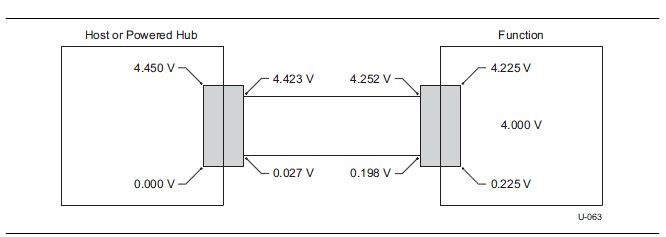
Maximum allowed worst case scenario within spec:
USB 2.0
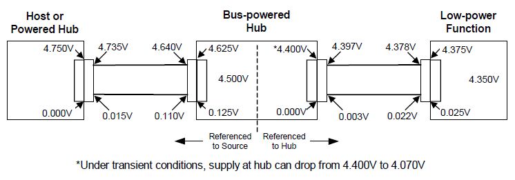
USB 3.x