
Full/Low Speed Signal Quality
USB 2.0
Specification, Chapter 7.1.2
For the full or low speed signal quality measurements USBET and USBHSET can be used. This measurment is also called the EYE diagram or signal integrity test. For the upstream measurement an enumeration of the device or hub is enough in order to perform these tests so products do not have to be in the final stage to perform these tests. (No window drivers are required for these tests). For an embedded host or OTG host side it's enough to capture a Full Speed SOF that is send every 1ms as a keep alive to a device. These tests are done behind 5 hubs for devices(*), behind 4 hubs for hubs and directly to the port on an embedded host or OTG Host side. For a Full Speed device or hub that has a standard B-receptacle the measurement is done after 5m cable; for a mini-B receptacle 4.5m cable; for mirco-B 2m cable. For an embedded host or the OTG host downstream side it's done behind 5m cable. If a device or hub has a captive cable, vendor specific cable or direct A-plug the measurement is measured as it is and no additional cable is added.
Probing should be done on a fixture.
The Low Speed upstream measurement is the
same
as Full Speed however Low Speed devices MUST always have a captive or
vendor specific cable (standard receptacles are not allowed). Therefore
the measurement of a low speed device is done as it is. Downstream Low
speed signal quality is directly done at host port by connecting a
supported low speed device without additional cables.
The Low Speed Downstream Signal Quality for an Embedded Host
should only be performed when the host support Low Speed
devices devices (has low speed devices on their TPL).
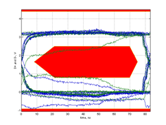
Make sure you capture the correct packet. Since the up and downstream signal is on the same D+/D- you migth capture the wrong packet so make sure you have the correct packet. If you have the wrong packet you typically get following result:
Note that it is allowed that the first bit of the SOF and last bit (EOP) are off therefore they should be excluded in the calculations.
High Speed devices also must undergo this test since a High
Speed device must support legacy speed.
It is advisable to perform these tests in an early stage of the
development.
Using a certified USB silicon will give a USB developer a certain guarantee that the product is capable of passing the eye diagram test. However, there are still many items that could cause the device to fail the eye diagram.
Common failures are:
- Bad PCB design (traces too long, traces not matched, interference
from another source,...)
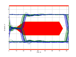
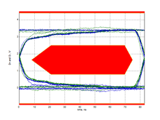
- Bad cabling. Below a full speed measurement on the same
device
after 5m cable with the left picture a good cable and right side a bad
cable.
- ESD, EMI components that do not meet the USB
requirements
- Bad clock, PLL
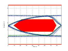
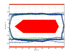
- Ferrite beads and common mode chokes. Below a full
speed measurement on the same device with the right
picture
the device with common mode chokes and on the left side the chokes
removed.
- Not use the latest USBET
- Bad Test Fixtures
(*) TIP
It
is possible to measure the upstream full or low speed EYE without the 5
tier of hubs since this has no effect on the signal integrity it self.